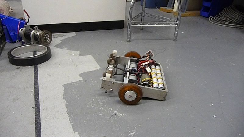
Last night, I went out to Hydrogel (where my dad works, and where we have access to a full machine shop, and where we will be doing most of our building) with the goal to make both bots work. Demansi Olivacea runs, but the drive motors suck. The gears in the gearboxes are all stripped, so they don't drive the wheels. The motor spins, and makes noise, but the wheels don't move. The weapon motor spins up really nicely, and I forgot how powerful the little weapon on the front could be if it was heavier. It's still pretty impressive even when it's this small. There are YouTube videos of me testing it from last night.
(1) and (2).
The repairs necessary for Copperhead III from last year's competition were:
- new wheels
- new motor mount brackets

- new front posts
- switch drum spin controller for a speed controller
- new battery mount system
- WEIGHT
- new Lexan top/bottom armor (not urgent)
- fix broken ring terminal for weapon system
- wire batteries in parallel
- cooling for batteries
We have bought tires for the new wheels, and I have made new front posts. I made new motor mount brackets as well, but they may be temporary if we cannot lighten them. I re-soldered the ring terminal for the switch for the weapon system, and I welded the nuts to hold the front posts to the frame. This was a very important fix, and should help signif
 icantly. On a "construction notes" note - when wiring the PWM cables to the R/C chip - for a fifteen pound bot, you do not need a separate cable for battery power to the receiver chip IF your speed controller has a built-in BEC (battery eliminating circuit - it will step down a high voltage to five or six volts and send that through the PWM cable to the receiver chip). The two drive motors wire to AILE and ELE (aileron and eleron functions - associated with the right stick on the controller - they automatically mix with the Spektrum DX6.1 controller so you can drive with one stick. And the weapon wires to the throttle. You need to train the voltage regulator (a.k.a. speed/spin controller - if you can) so that if you have a spin controller, then full negative throttle outputs 0V and full positive is 100% (or you can cut it back so max is 80% or whatever you choose). If you have a reversible speed controller, then full negative throttle needs to be 100% voltage (or your max) in the reverse direction and full positive is 100% voltage in the forward direction. This training process varies among all the speed/spin controllers out there - each one is different.
When wiring the BR6000 bot receiver (which is the one we are using) the black lead for the PWM cable goes to the negative (ground) terminal on the receiver - white is signal, red is positive, and black is ground. The particular spin controller we used in the 15 lb bot, a SpeedMax-40 spin controller [they call it a speed controller but it's non-reversible, so I call it a spin controller] has brown, red, and orange leads. The orange is signal, red is positive, and brown is ground.
The wiring for this bot is pretty efficient and works well, so I am going to suggest a setup similar to this for when you design your bots (if applicable).
-2 geared drive motors (one right, one left)
-1 weapon motor (a 12V deWalt drill motor works well - it's quite powerful)
-for a non-reversible weapon, the SpeedMax-40 sc works great - it's fully programmable
-for the drive motors, a double speed controller with BEC - Sabertooth 25 Dual 25A Motor Driver
-two 12V battlepacks with PowerPole connectors
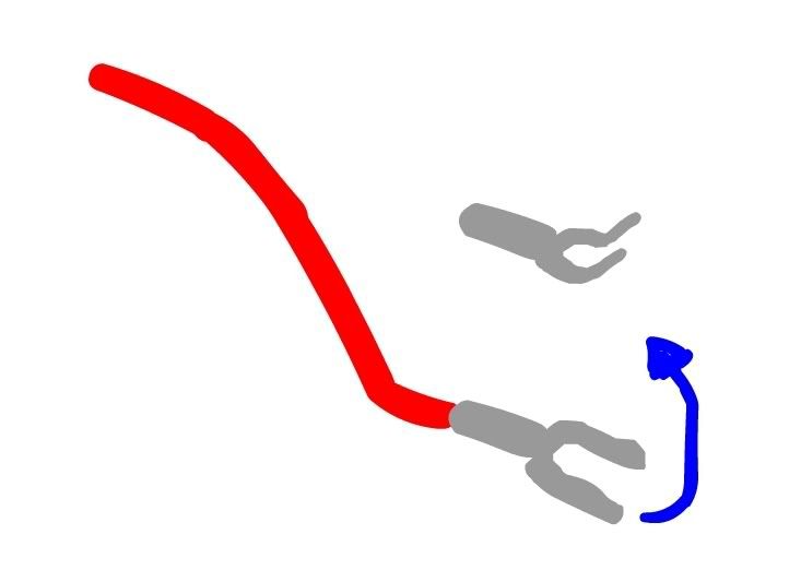
1) wire the batteries in parallel so you keep the 12V rating, but double the current
--> do this with Y cables - you can make them yourself, they're just a pain, have two PowerPole connectors and two prong (fork) terminals.
2) wire a switch interrupting the + battery lead. I will refer to the + battery lead as the lead that comes AFTER the switch.
3) the double speed controller has six big input/output terminals on one side, and four small inputs on the other. The big terminals are the power in/out and motor connections, and the others are PWM connections (you have to take the PWM connector terminals off that end of the PWM cable to screw them into the terminal blocks).
--> the middle two big terminals are for the batteries. They are labeled + and -. RED is ALWAYS positive. Bend the prong connectors into a 60 degree angle so that they can interface with the two terminals, and attach them to the BACK side of the terminal. Then attach the stripped wire leads (red + black) of the SpeedMax SC to the + and - battery teminals. This is so that the SC [spin controller] has power and can function, regardless of whether the dual SC is outputting voltage to the drive motors. These two systems MUST be independent. The pair of terminals on either side of the battery terminals are for the motors (R and L) and the wiring is simply a + and - stripped wire lead for each motor.
--> the four small terminal blocks on the other side of the dual SC are for the PWM cables. Leave one end of each PWM cable with a connector on it, and leave stripped wire ends for the other side. Attach the connector side to the appropriate spot (AILE or ELE) on the receiver chip. A PWM cable has three leads - two for power (+V and ground) and one for the signal. The two grounds (blacks) and the two +V's (reds) each pair up, and wire into the 0V and 5V terminals, respectively. 0V is for the grounds, and 5V is for the + leads. The S1 and S2 terminals are for the white signal leads from each PWM cable - depending on which cable is ELE and which is AILE, they will either go to S1 or S2. You may need to experiment to determine this. (the manual for the dual SC)
4) the SpeedMax SC's yellow stripped wire leads are labeled M+ and M- and go to the + and - terminals on the weapon motor. The PWM cable goes to the receiver chip - brown is signal, orange is - and red is +.
This should be all the wiring necessary for a simple 3-motor small bot.
2 comments:
so... should i bring in the pool, or not?
you don't have to. Sorry this plan fell through, but it would have been cool if it worked. R/C CARS! we need them!
Post a Comment